Magnetic Induction Voltage Regulator Operation
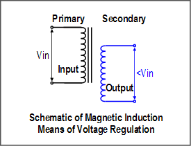 Another means of changing output voltage in a transformer is to alter the physical orientation of the primary and secondary relative to each other. In a transformer the primary windings produce a magnetic flux field that induces current to flow in the secondary windings. Physically repositioning the windings of the secondary within the flux field can change the amount of current induced and the output voltage.
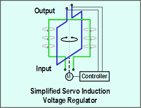 The magnetic induction voltage regulator (or servo induction voltage regulator) changes the orientation of the transformer secondary relative to the magnetic field rather than changing taps. The magnetic induction voltage regulator may look like an electric motor having the primary windings in a cylindrical, stationary configuration (stator) and the secondary windings (rotor) inside the primary wrapped around a shaft that is supported by bearings. Unlike a motor, the secondary of the servo induction voltage regulator rotates back and forth in an arc less than 360 degrees to alter the output voltage. Like a tap switching voltage regulator, a controller measures the output voltage and uses a servomotor drive to adjust the degree of rotation of the rotor to achieve the desired output voltage.
In both, tap switching and servo induction voltage regulators, the control mechanisms range from simple analog devices to microprocessor-based controls with onboard data acquisition and communication capabilties. Falling costs, high accuracy, solidstate designs and programability favor increased use of digital controls, however analog controls can be very inexpensive and tolerant of higher temperatures.