Applying a voltage regulator/power conditioner is simple. As with any electrical product, care must be taken to ensure that all national, state and local codes are observed, and that the specifying, installation, operation and maintenance of voltage regulator/power conditioner are conducted by qualified professionals.
Application
The first rule in applying a voltage regulator/power conditioner:
Place the voltage regulator/power conditioner between the source of the power problem and the equipment to be protected. A corollary to this rule is placing the voltage regulator/power conditioner immediately ahead of the equipment to be protected in order to provide maximum protection. The sources of power quality problems can be external, internal or both.
External causes include undervoltage, sags, surges or other problems initiated on the electrical transmission or distribution network outside the end user’s facility. The main electrical service entrance is the point of entry into the facility.
Internal causes tend to be sags and undervoltage created by large electrical loads or loads with high inrush current. Motors, magnets, transformers and welders are examples of internal loads that frequently cause power quality problems that can affect other equipment.
For example, a facility subject to chronic undervoltage because of its location in a large industrial park may install a new CNC tool. When the tool starts, the large inrush current depresses the already low voltage to the point that other equipment malfunctions. This is a typical example of external and internal conditions combining to cause a symptomatic power quality problem.
The following are reasons to apply a voltage regulator/power conditioner:
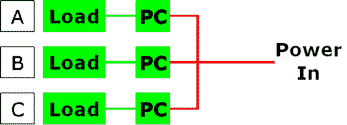
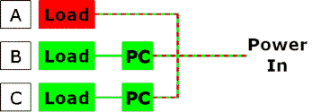
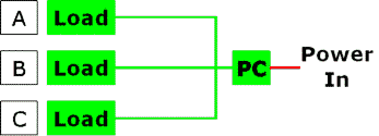
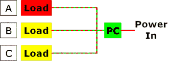
- Red lines indicate poor power delivery
- Green lines indicate protected power delivery
- Red and green lines indicate power delivery that can be intermittently good and poor
 Single phase voltage regulator/power conditioners have simple input and output connections (generally, two “hot” lines in and two “hot” lines with a new ground coming out). In some cases, a single-phase unit might be supplied with a line coming from an extra “tap” on the secondary in order to provide single-phase output voltages at two convenient levels, such as 240v and 120v. This arrangement is sometimes referred to as a “split phase.”
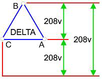
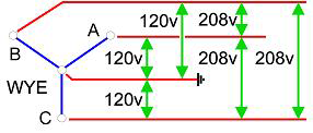 Voltage regulator/power conditioners in three-phase applications typically utilize a “delta” input and a “wye” output, which is the most common arrangement in industrial and commercial applications. The “wye” output is particularly useful since it allows output voltage at two different levels (line-to-line and line-to-neutral) and provides a new ground reference for downstream devices.