Circuit Breaker
A circuit breaker provides protection from short circuits and overcurrent for the power conditioner and equipment and wiring downstream of the power conditioner, regardless of upstream events.
Correction Duration
Correction duration is the length of time that a power conditioner can correct a power quality event. Power conditioners that rely on energy storage (e.g. capacitors, batteries, flywheels) as their primary means of conditioning may not be able to provide correction for events that last for more than a few cycles or seconds or if several severe events happen in rapid succession. Power conditioners that do not rely upon energy storage generally provide unlimited correction time.
Efficiency
Efficiency simply refers to the power coming out of a unit divided by the power going into a unit, usually expressed as a percentage. All voltage regulators and power conditioners “consume” energy in the process of performing their task.  Typically this consumption is in the form of losses that occur within components (e.g. transformers) where lost electrical energy is converted to mechanical energy in the form of heat or motion (vibrations). Efficiencies can run the spectrum from 50% to 99%. Most units have efficiencies that are relatively constant across the load range. Ferroresonant transformer-based units, however, tend to have efficiencies that fall off very quickly for points below full load. Efficiency may be one of the most overlooked parameters when selecting a voltage regulator or power conditioner. A quick gauge of efficiency cost differences can be calculated by multiplying the unit’s KVA size by the difference in efficiency by 7. The result is an approximation of the annual energy cost difference (at $0.08/KW-HR) in dollars. For example, for 25 KVA units with a 3% difference in efficiencies, the unit with the lower efficiency would cost about $525 more per year in extra energy consumption.
Electronic Bypass
With many power conditioners, when a malfunction occurs, the power conditioner shuts off and the power for the load is lost. For mission-critical equipment, this is unacceptable. An electronic bypass allows the power conditioner to provide unregulated power to the load, even in the case of component failure. In addition to not dropping the load, the electronic bypass protects the load in the event of a component failure in the power conditioner. For some power conditioners, a component failure or malfunction could result in potentially damaging output voltages being sent to the load.
Fault Clearing and Overload Capacity
This term describes a unit’s ability to tolerate current levels higher than the rated current without sustaining short- or long-term wear or damage. Many electric devices, including motors, magnets, and transformers, require a large inflow of current when started (inrush current). A “typical” AC motor has an inrush of 500% to 1,000% of the normal current that peaks in a few cycles and then drops to normal levels within 10 to 30 cycles. Power conditioners with ratings of 1,000% for one cycle might not be good choices for industrial or commercial applications with frequent or large inrush current. The higher the percentage and the longer the time spent at that percentage, the better the unit should stand up to high inrush applications. Fault clearing is related to overload capacity, as both describe the power conditioner’s ability to operate at current levels above the unit’s rating. If a power conditioner cannot pass enough current without tripping or shutting down, downstream equipment and protective devices may not be able to “clear” or reset themselves, creating an operational problem.
Harmonic Distortion
Harmonic distortion is an alteration of the voltage waveform by the power conditioner (making it appear jagged rather than smooth). The less distortion, the better.
Voltage regulators that operate by switching taps (tap changing), particularly electronic voltage regulators, can cause a phenomena known as “notching.” If the waveform is not at zero (the point at which it crosses the horizontal axis), the output voltage waveform will be distorted when the regulator changes taps.
Impedance
Impedance is the opposition to the flow of electrons in an AC circuit as a function of the circuit’s resistance, capacitance and inductance. Impedance in an AC circuit is analogous to resistance in a DC circuit. Even simple wire conductors have properties of resistance and inductance that affect the impedance of an AC circuit. High impedance can have a significant impact on power quality because it directly affects voltage as a function of the current flow. For example, a device drawing 1A on a circuit with a 1 ohm impedance and a 100V source will see 99V. If that same device draws 10A, it would see only 90V. The same device on a circuit with a 0.1 ohm impedance would see 99.9 and 99V, when drawing 1 and 10A, respectively. A circuit or system with a low impedance is said to be “stiffer” than its high impedance counterpart because the voltage changes less as a function of the current.
Independent Phase Regulation
In three-phase applications, the incoming voltage level of each phase is frequently unbalanced (e.g. Phase A = 440v, Phase B = 469v, Phase C = 453v). This unbalance can cause many electric devices, such as motors, to run inefficiently, causing them to run at higher temperatures and wear out prematurely. Units that offer independent phase regulation provide much more accurate voltage regulation and a higher level of protection than units that assume that phase voltages are balanced.
Input Range
Input range is the percent deviation above and below the nominal (or rated) input voltage that can be corrected to within the specified output regulation. In other words, this is a measure of how widely the input voltage can vary from the recommended voltage. The larger the “spread,” the better (e.g. +10% to -25% provides a wider input voltage window than ±10%). For a nominal 480v input voltage, an input range of +10% to -25% equals 528v to 360v.
Size (kVA)
The kVA sizes available. (See calculating kVA sizes.)
Line Isolation
Line isolation is the electrical separation of incoming and outgoing power through an isolation transformer. These transformers reduce noise and transients present in the incoming power. The efficiency of units using an isolation transformer are typically two or three percentage points lower than units that do not provide line isolation.
Load
A load is a device or collection of devices that draw energy from the electrical system. The load can be made up of active (motor, variable frequency drive, etc.) or passive (resistor, inductor, capacitor, etc.) components. (See power factor.)
Load Power Factor and Power-Factor Limitation
Devices such as transformers and motors require power to maintain magnetic fields to perform. This “reactive” (kVAR) power flows into and out of the device but is not consumed to perform. The power that is consumed is called “real” (KW) power. The vector sum of reactive and real power is called “apparent” (kVA) power. Power factor (PF) is the ratio of real power to apparent power. The terms “leading” and “lagging” refer to reactive power put in or taken out by the device. leading power factors are rare. Lagging power factors can range from 0.4 to 0.99. For power conditioners, limitation on load power factor is generally required if the unit will not operate or respond properly when the power factor is too low. Unless the power factor of existing or future devices to be protected are well known, it’s best to select power conditioners with no (or minimal) load power-factor limitations.
Minimum Load
Power conditioners are frequently used to protect circuits with multiple loads. If the power conditioner requires a minimum load to operate properly, care must be taken to coordinate starting and stopping individual loads.
Noise Attenuation
Noise attenuation (reduction) is a common power conditioner feature. Electrical noise reduction is measured in decibels (db). The db is a logarithmic ratio of intensity or, in the case of electrical noise, the amplitude of one noise voltage level to another. For example, a 40 db reduction in noise means that the incoming noise is reduce by a factor of 10,000.
There are two types of reduced noise: common mode and normal mode.
Common mode noise exists between the ground and the neutral. Electronic devices are most sensitive to common mode noise. A shielded isolation transformer is very effective in reducing common mode noise.
Normal (or transverse) mode noise exists between the “hot” lines and the neutral. Normal mode noise is generally reduced with a shielded isolation transformer.
Operating Frequency
Voltage regulators and power conditioners come in 50 or 60 Hertz (frequency) or, in some smaller units, dual frequency (both 50 and 60 Hz). The USA, Canada, Mexico, Puerto Rico, South Korea, Taiwan and the Philippines use 60 Hz. Europe, most of Asia and Africa and Australia use 50 Hz. Latin American and Caribbean countries are a mix of 50 and 60 Hz, depending upon the country. Some countries such as Japan, Saudi Arabia and Brazil use both operating frequencies.
In most developed countries, electric frequency deviates very little from the standard. A deviation of even .5 percent is considered unusual. For this reason, the operating frequency of a power conditioner is generally not an issue. In countries with very unstable electrical systems or in facilities using a power conditioner behind a generator, frequency of operation can become an issue. Most power conditioners do not correct frequency. If frequency correction is required, it typically occurs separately, ahead of the power conditioner.
Output Regulation
Output regulation is the percent deviation above or below the nominal (or rated) output voltage when the incoming voltage is within the input range. Smaller numbers mean more precise regulation. An output regulation of ±3% is well within the tolerance required by the vast majority of electric devices. For special applications such as laboratory testing or calibration, an output regulation of ±1.5% or less may be more desirable. For a nominal 208v output, ±3% output regulation equals 214v to 202v.
With many voltage regulators, there will be a direct correlation between the input range and the output regulation. As the output regulation gets smaller, the input range will also get smaller. This is due to the fact that manufacturers will have a fixed number of points or taps at which changes in output voltage can be made. To decrease the output regulation percentage without decreasing the input range requires adding more taps, resulting in a custom (and more expensive) design.
Phase
Phase refers to the availability of single- and three-phase AC models.
Response Time
Response time is the time it takes a unit to respond to deviations in incoming voltage. The shorter the time, the better the unit is at keeping voltage within the output regulation range.
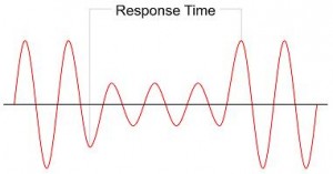 “Correction time” is another term that often appears in specifications. This refers to the time that it takes for a unit to adjust the output voltage to within the output regulation range, once the unit has begun to respond.
The total time it takes a unit to correct low or high voltage is the response time plus the correction time.
Electronic voltage regulators are so fast that response time and correction time are frequently used interchangeably. On the other hand, mechanical voltage regulators have a response time similar to that of the electronic units, but their slow correction time (measured in seconds) is a limiting factor.
Ride-Through
“Ride-through” refers to a device’s capability to correct or withstand a certain type of power quality issue. Typically, ride-through is used in conjunction with sags or interruptions. (See correction duration.)
Size (kVA)
The kVA sizes available. (See calculating kVA sizes.)
Snubber
A snubber is a filter that blocks high-frequency, high-voltage transients not typically handled by other means.
Surge Suppression
Surge suppression provides protection for the power conditioner and downstream equipment against large “surges” of voltage that can happen during transient events, such as lightning strikes or transmission/distribution equipment malfunction. Surge suppression is often accomplished with metal oxide varistors (MOVs), zinc oxide, or surge capacitors.
Technology
Motorized variable transformer units use motors to physically move or reorient unit hardware to regulate output voltage. These units can offer very precise regulation and good overload capacity, but they have slow response times and require regular maintenance. Electronic tap changers offer good regulation, fast response times, and have no moving parts, but some units have poor overload capacity.