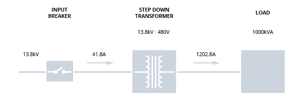
FIGURE 1: Example System – 13.8 to 480V. 1000kVA Load. Diagram represents a 3-phase system. Voltage is line to line. Currents are per phase.
The example base system depicted as Figure 1 has a sample input of a 60Hz 13.8kV phase-to-phase supply with a maximum load of 1000kVA at 480 volts. In optimal conditions (no voltage swells or sags), the power supplied to this base system at 13.8 kV would be reduced to 480 volts with a 13.8kV to 480 step-down transformer. As noted in Figure 1, the current on the 13.8kV line would be 41.8 amperes when the load is at its maximum level of 1000kVA, and the transformer would be rated and designed to carry this current level. The current on the low-voltage side would then be 1202.8 amperes per line (the same current necessary to supply power to the load at 480 volts). Normally, the input breaker trip level would be set at 133% of full-load current – or 55.6 amperes.
For purposes of this discussion, the regulator is located on the low-voltage side of the transformer. (If the regulator were to be placed in front of the step-down transformer, the analysis would be similar and the conclusions identical.) This discussion also assumes that the regulator in Figure 1 mitigates voltage swells of up to 10% and sags down to 75% (-25%) of nominal voltage. This level of capability addresses the vast majority of system power-quality events and is representative of commercially available voltage regulators applied on the low-voltage side of a step-down transformer.