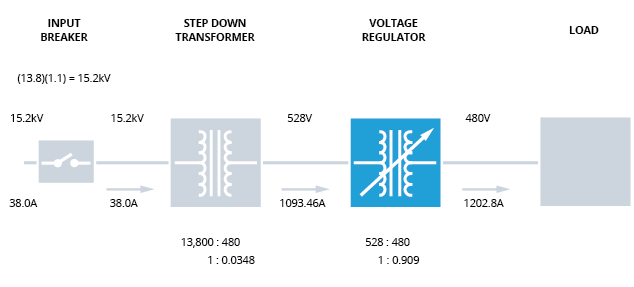
FIGURE 3: Input voltage 10% high. Regulator reduces voltage from 528 to 480.
Figure 3 illustrates voltages and currents on the input and output of each system component.
In this case, it is assumed that the system delivers power with a voltage of 110% of nominal. A 13.8kV nominal system, for example, would have an input voltage of 15.2 kV. Since the load is 1000kVA, the current flowing through the input breaker will be 38.0 amperes. Since the step-down transformer has a fixed turns ratio, the secondary voltage will be 528 volts (rather than 480), and the secondary line current will be 1093.46 amperes.
To address (correct) this issue, the voltage regulator will recognize the higher-than-desired input voltage and adjust its turns ratio accordingly. That means that the regulator’s turns ratio will adjust to 1.0 to 0.909 to reduce input voltage to the desired level. The voltage on the regulator’s output will be 480 volts, and the current will be the 1202.8 amperes established by the load. Both the step-down transformer and the regulator must be capable of withstanding a voltage of 10% high to manage this issue effectively.

